


Understanding CT Meter Panel Fundamentals and Architecture
For commercial and industrial facilities, precise measurement and management of significant electrical loads are critical. Standard residential meter sockets simply cannot handle the high amperages or voltages, such as 480 VAC, common in these larger applications. When electrical service exceeds 200 Amps or 400 Amps, depending on regional utility standards, specialized metering solutions become essential.
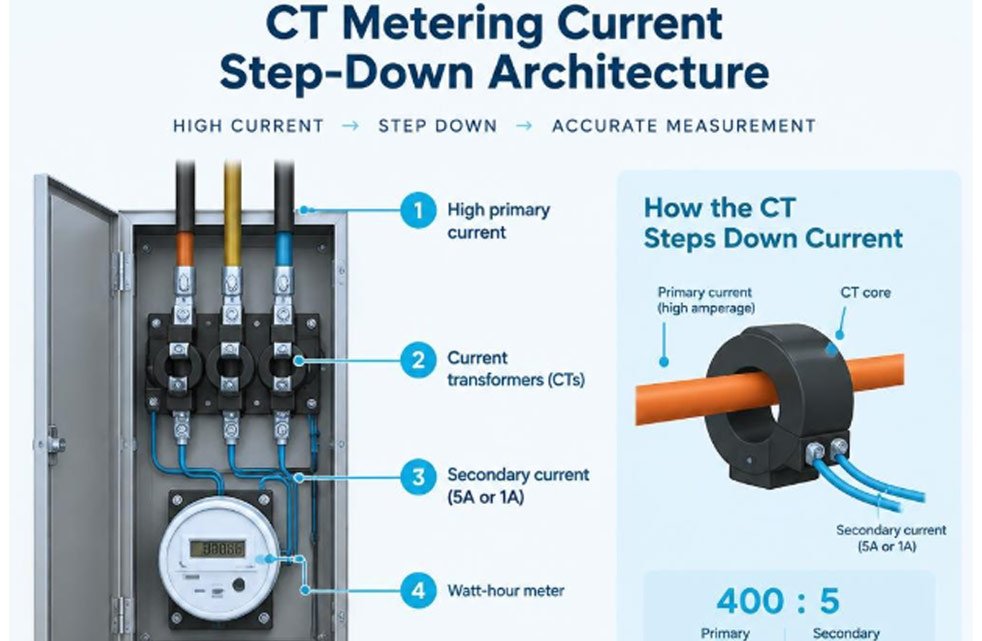
This is where Current Transformer (CT) meter panels come into play. These sophisticated systems are vital for accurately monitoring electricity consumption, ensuring compliance with utility requirements, and maintaining worker safety during maintenance. They effectively step down high primary currents to a lower, measurable secondary current for the electric meter.
This comprehensive guide will explore the fundamentals of CT meter panels. We will delve into their core principles, differentiate between various types of current transformers, examine key specifications, and outline crucial installation best practices. Understanding these components is vital for ensuring accurate revenue metering, system efficiency, and the safety of utility personnel. For those seeking durable and precise solutions, exploring options like Weschler rugged CT meter panels can provide valuable insights into high-quality metering equipment designed for demanding environments.
A CT meter panel is a specialized electrical enclosure designed to house current transformers (CTs) and a watt-hour meter for accurately measuring high-amperage electrical services. Unlike standard residential meter sockets, which directly measure current up to a certain limit (typically 200 Amps), CT meter panels utilize current transformers to “step down” the high primary current to a manageable secondary current. This induced secondary current, usually 5 Amps or 1 Amp, is then safely fed to a revenue-grade watt-hour meter.
Utilities mandate CT metering for services exceeding specific amperage thresholds, which can vary by region. For instance, in EUSERC (Electric Utility Service Equipment Requirements Committee) regions in the western United States, CTs are typically required for applications above 200 Amps. In most other areas, this requirement generally applies to services over 400 Amps, particularly at higher voltages like 480 VAC. This requirement is not only for accurate billing but also for the safety of utility personnel, as it prevents high currents from directly flowing through the meter itself.
Some CT meter panels are designed as “transockets,” which integrate both the CT section and the meter socket into a single, consolidated enclosure. This design can save space and simplify installation, especially in regions like the American Southwest where they are commonly specified. These specialized enclosures, often found at commercial and industrial service entrances, ensure that the utility can safely and accurately measure electricity consumption for billing purposes.
CT Metering Principles and Primary vs Secondary Current
At the heart of a CT meter panel’s operation is the principle of magnetic induction. A current transformer functions by creating a proportional electric current in its secondary winding based on the primary current flowing through the conductor it encircles. The primary current, which is the high-amperage current of the electrical service, passes through the CT’s core. This induces a much smaller, proportional secondary current in the CT’s secondary winding.
This “step-down ratio” is crucial. For example, a 400:5 CT will reduce a 400-Amp primary current to a 5-Amp secondary current. This 5A or 1A secondary current is then safely routed to the watt-hour meter. The meter is calibrated to multiply the measured secondary current by the CT’s ratio to display the actual primary current consumption.
Several factors are vital for the proper functioning of CTs. The “secondary burden” refers to the impedance of the metering circuit connected to the CT’s secondary terminals. Exceeding the CT’s rated burden can lead to accuracy issues. “Core saturation” occurs when the primary current is too high for the CT’s core, causing the secondary current to no longer be proportional, leading to inaccurate readings. To ensure accuracy, CTs are designed to operate within a specific “operational threshold,” typically ranging from 5% to 120% of their rated value. For example, a 400A CT should ideally measure currents between 20A and 480A for optimal accuracy.
Window vs Bar Type Current Transformers
Current transformers come in various configurations, with “window” (or “donut”) type and “bar” type being two primary designs. The choice between these depends on the specific installation requirements, conductor type, and space availability.
Window CTs, also known as donut CTs, are designed with an open central window through which the primary conductor (cable or busbar) passes. They do not have a built-in primary winding; instead, the system’s live conductor acts as the primary. These are highly versatile and commonly used when retrofitting existing installations or when the primary conductors are continuous cables. Their installation involves passing the conductor directly through the CT’s opening.
Bar-type CTs, conversely, feature an integrated permanent bar that functions as the primary conductor. This bar is typically made of copper or aluminum and is housed within the CT’s enclosure. The main service conductors are then connected directly to this bar using lugs. Bar-type CTs are often preferred for new installations, especially in higher amperage applications (e.g., 400A to 800A service), as they can simplify wiring by providing a direct connection point and often help manage conductor bend radii within the panel. They are commonly associated with specific mounting bases that feature 1/2-inch studs on 1-3/4-inch centers for secure attachment.
Feature Window (Donut) Type CTs Bar Type CTs Mounting Footprint Flexible, depends on conductor routing Fixed, often larger due to integrated primary bar Conductor Capacity Accommodates various cable/busbar sizes passing through Specific to the integrated bar’s current rating and size Installation Complexity Requires routing primary conductor through opening Connects primary conductors directly to integrated bar Primary Winding None (primary conductor acts as winding) Integrated permanent bar Best Use Case Retrofits, existing continuous conductors New installations, high-amperage services, compact panels Bar-type CTs, particularly when integrated into mounting bases, can offer significant labor and cost savings compared to traditional wood panel cabinets. They consolidate multiple components, reducing the number of individual attachments needed during installation.
Technical Specifications and Engineering of Weschler Rugged CT Meter Panels
The engineering and specifications of CT meter panels are critical for ensuring accurate, reliable, and safe operation in demanding industrial and commercial environments. These panels must meet stringent industry standards, such as ANSI C12.20 for revenue metering, which specifies accuracy classes for watt-hour meters and associated instrument transformers.
Key specifications include voltage ratings (e.g., suitable for 480 VAC systems), accuracy class (e.g., 0.5% or 1% accuracy), and the CT’s dynamic range. The dynamic range indicates the span of primary current over which the CT maintains its specified accuracy, typically 5% to 120% of its rated value. Environmental considerations are also paramount, dictating the required NEMA enclosure ratings (e.g., NEMA 3R for outdoor use) to protect components from dust, moisture, and temperature extremes. Thermal stability and burden rating are also important, ensuring the CT can handle the heat generated by current flow and the impedance of the connected metering equipment without compromising accuracy or longevity. For those seeking durable and precise solutions, exploring options like Weschler rugged CT meter panels can provide valuable insights into high-quality metering equipment designed for demanding environments.
Sizing and Ratio Selection for Weschler Rugged CT Meter Panels
Selecting the correct CT current ratio is paramount for accurate metering. The ratio must be chosen based on the maximum expected primary current of the circuit, ensuring it falls within the CT’s operational range. For instance, a circuit with a maximum expected load of 350 Amps would typically use a 400:5 Amp CT. Most CTs are designed to operate accurately between 5% and 120% of their rated value, with a common accuracy rating of +/- 1%.
When sizing, it’s also essential to consider the physical dimensions of the primary conductors. The CT’s window opening or bar size must be large enough to accommodate the conductor diameter. General guidelines for CT amperage ratings based on circuit size are:
- 10A-30A circuits: 20A CT
- 30A-70A circuits: 50A CT
- 70A-225A circuits: 150A CT
- 225A-500A circuits: 300A CT
- 500A-800A circuits: 600A CT
- 800A-1600A circuits: 1000A CT
- 1600A-2500A circuits: 2000A CT
For service applications, it’s a best practice to select a CT mounting base with a rating higher than the service amperage. For example, a 600-Amp service application would typically utilize an 800-Amp rated current transformer mounting base to ensure robustness and proper phase spacing.
The distance between the CT and the meter also impacts wiring. Standard CT factory lead wires are often around 3 feet long. While it’s generally recommended to keep lead lengths short, CT wires can be extended up to 30 feet using 22-gauge twisted pair extension wire, provided the secondary burden limits are respected. However, cutting factory wires can sometimes invalidate manufacturer warranties, so consulting the CT manufacturer’s guidelines is advisable.
Safety Mechanisms in Weschler Rugged CT Meter Panels
Safety is a critical consideration in CT meter panel design, particularly for utility workers who perform maintenance or meter replacements. CTs, by nature, are inductive devices. If the secondary circuit of an energized CT is left open, it can generate extremely high, dangerous voltages across the secondary terminals, posing a severe arc flash and shock hazard. This phenomenon is known as “secondary open-circuit.”
To mitigate this risk, CT meter panels incorporate several safety mechanisms:
- Shorting Blocks: These are terminal blocks designed to automatically or manually short-circuit the CT’s secondary windings when the meter is removed or during maintenance. By providing a low-impedance path, they prevent the dangerous voltage buildup.
- Test Switches: Often integrated into the meter socket or as separate components, test switches allow utility personnel to safely isolate the meter from the CTs and shunt the CT secondary circuits without interrupting the primary load. They typically have multiple positions for testing, bypassing, and isolating.
- Bypass Mechanisms: These mechanisms provide a way to safely remove or replace the watt-hour meter without de-energizing the main service.
- Auto Bypass (Plunger Bypass): This common type automatically shorts the CT secondary circuits when the meter is physically removed from the socket.
- Heavy-Duty Lever Bypass: Found in some higher-amperage meter sockets, this mechanism uses a lever to manually engage bypass blades, shunting the CT secondary and allowing for meter removal.
Bypass Option Description Activation Method Primary Benefit Auto Plunger Bypass Integral plungers automatically shunt CT secondaries when meter is removed. Automatic Enhanced safety during routine meter changes Heavy-Duty Lever Bypass Manual lever engages bypass blades to shunt CT secondaries. Manual Robust isolation for high-amperage services, visual confirmation Manual Test Switches Dedicated switches allow manual shorting, testing, and isolation of CTs. Manual Comprehensive testing and maintenance flexibility These safety features are essential for protecting utility workers from the hazards of high voltage and arc flash during meter replacement and maintenance operations, ensuring that the CT secondary circuits are always safely shunted.
Installation Best Practices and Multi-Phase Wiring Configurations
Proper installation of CT meter panels is crucial for both accurate metering and long-term reliability. This involves careful attention to load polarity, phase sequence, and the correct integration of all components, including test switches and digital interfaces. Whether monitoring a simple subpanel or a complex three-phase 4-wire delta or wye system, adherence to best practices ensures optimal performance.
One critical aspect is understanding load types. Balanced loads, such as HVAC units or electric resistance heaters, draw roughly equal current on all phases. In some specific monitoring applications (not revenue metering), a single CT might be used on a double-pole breaker for a balanced load, with the monitoring system multiplying the reading. However, for revenue metering and most accurate subpanel monitoring, each phase requires its own CT. Unbalanced loads, like clothes dryers, ovens, or subpanels serving mixed loads, draw different currents on each phase and typically involve a neutral conductor. For these, dedicated CTs are essential for each phase to capture accurate consumption.
Phase Alignment, Polarities, and Test Switch Integration
Correct phase alignment and polarity are non-negotiable for accurate CT metering. Each CT must be installed on the correct electrical phase, matching the meter’s wiring manual. Incorrect phase alignment will lead to corrupted data and inaccurate energy readings.
The orientation of the CT is also vital. Most CTs have a directional arrow or a marked “K” and “L” terminal. The arrow should always point towards the load side of the circuit, or current should flow from the “K” terminal (grid side) to the “L” terminal (load side). Similarly, the secondary leads from the CT must be connected to the meter with correct polarity. Typically, white wires connect to positive CT pins and black wires to negative CT pins, ensuring that the induced secondary current flows in the correct direction relative to the meter’s internal circuitry.
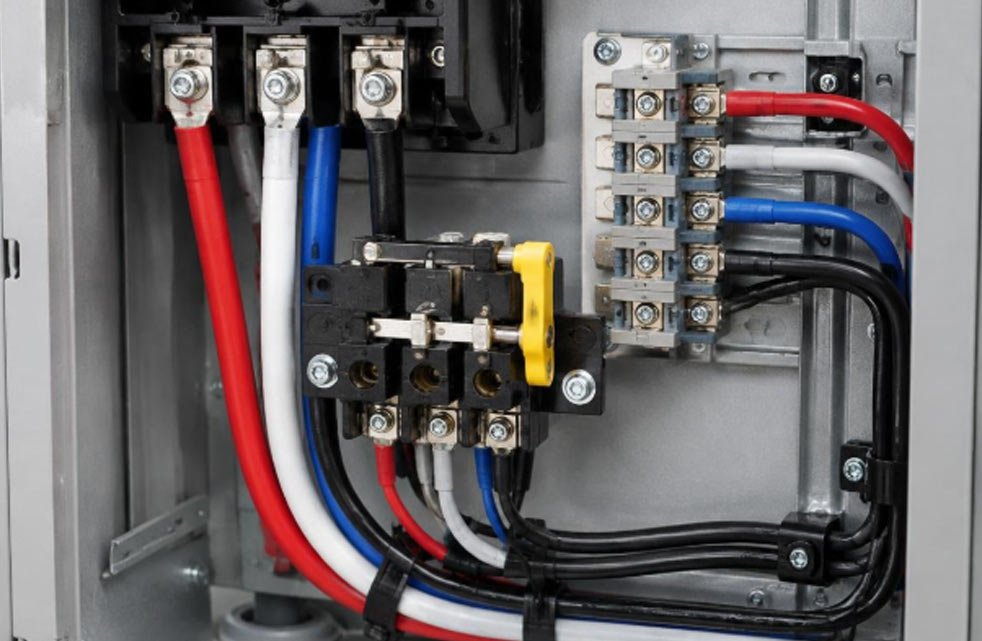
Test switches play a critical role in both safety and maintenance. They allow utility personnel to safely isolate the meter, short the CT secondaries, and perform tests without interrupting the primary power. Many CT meter sockets include “test perches” or integrated test switches. For higher voltage applications, potential transformers (PTs or VT packs) may also be used to step down the voltage to a safer, measurable level for the meter, further enhancing worker safety. Color coding of wiring is also a key best practice, helping installers and technicians quickly identify phases and connections.
Digital Interfaces and Monitoring System Integration
Modern CT meter panels increasingly incorporate digital interfaces for advanced monitoring and integration into building management systems. These energy meters often feature RS485 communication ports, enabling them to transmit data using protocols like Modbus RTU. This allows for remote telemetry, providing real-time data on active power, reactive power, power factor, voltage, and current.
For example, a three-phase smart meter might have a rated voltage of 3×230/400Vac and support a maximum reading of 9999999.9kWh/kVArh, with an active power accuracy of 0.5%. Such meters can be DIN-rail mounted for easy integration into existing panels.
Digital outputs, such as pulse outputs, can also be provided for integration with older systems or for simple energy accumulation. The ability to sub-meter various loads within a facility provides granular data, enabling facility managers to identify energy waste, optimize equipment schedules, and verify the performance of energy efficiency initiatives. When integrating these meters, it’s crucial to confirm communication settings like baud rate (e.g., 9600 bps) and communication addresses to ensure seamless data exchange with supervisory control and data acquisition (SCADA) systems or energy management platforms.
Conclusion
CT meter panels play an essential role in accurate electrical metering, safe maintenance, and effective energy management in commercial and industrial facilities. Choosing the appropriate current transformer ratios, enclosure ratings, and safety features helps ensure reliable performance and compliance with applicable utility requirements. Proper phase alignment, polarity, wiring, and communication settings are equally important for accurate measurements and dependable monitoring. By prioritizing these factors and following manufacturer specifications and qualified electrical practices, facility managers and electrical professionals can support safer operations and more efficient energy management.
